OPTICAL FILTER
Fiber Fabry-Perot filters explained
A fiber Fabry-Perot tunable filter is specified by three numbers — and only two of them are independent.
A fiber Fabry-Perot tunable filter is specified by three numbers, and only two of them are independent. Understanding how they relate is the difference between ordering a part that does the job and ordering one that misses by a factor of ten. This page explains the relationship, works through the arithmetic on real catalogue references, and ends with a method for going from your requirement to a part number.
What a fiber Fabry-Perot tunable filter is
A Fabry-Perot cavity is two mirrors facing each other. Light entering the cavity bounces between them, and only the wavelengths whose round trip is an exact number of half-wavelengths build up constructively and are transmitted. Everything else is rejected. Move the mirrors closer or further apart and the transmitted wavelength moves with them — that is the tuning.
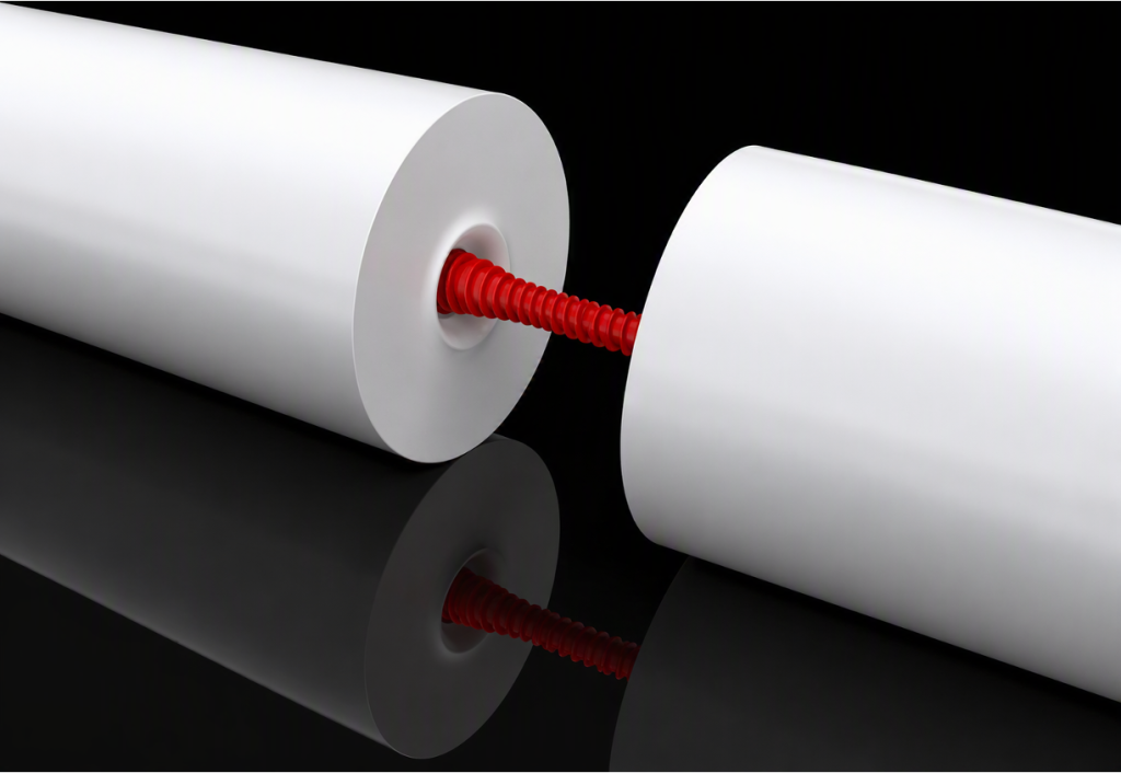
In a fiber Fabry-Perot filter, the mirrors are deposited directly on the polished ends of two optical fibers held facing each other, and one of them is mounted on a piezoelectric actuator. Light goes in through one fiber and out through the other. There is no free-space section, no collimation, and nothing to realign: the filter is a fiber-to-fiber component that drops into an existing optical path.
That construction is what makes very high finesse practical. The cavity is short — hundreds of micrometres — so the mechanical stability required to hold a resonance is achievable, and the mirror surfaces are small enough to be coated to very low loss.
The three numbers, and the one equation that links them
Free spectral range (FSR) is the spacing between two consecutive transmission peaks. It sets how far the filter can be tuned before it starts repeating itself, and therefore how wide a spectral window it can scan unambiguously.
Finesse is the ratio between the free spectral range and the width of a single peak. It is a pure number, governed by the mirror reflectivity and the losses in the cavity. It is not something you specify because your application needs it — it is the means, not the end.
Bandwidth is the full width at half maximum of one transmission peak. This is what your application actually cares about: it is the spectral resolution of the filter.
The three are tied by a single relation:
Δν = FSR / finesseEverything else on this page follows from that line. A narrower passband can be obtained by lowering the FSR, by raising the finesse, or by both — and those two levers have very different consequences, which is the subject of the next two sections.
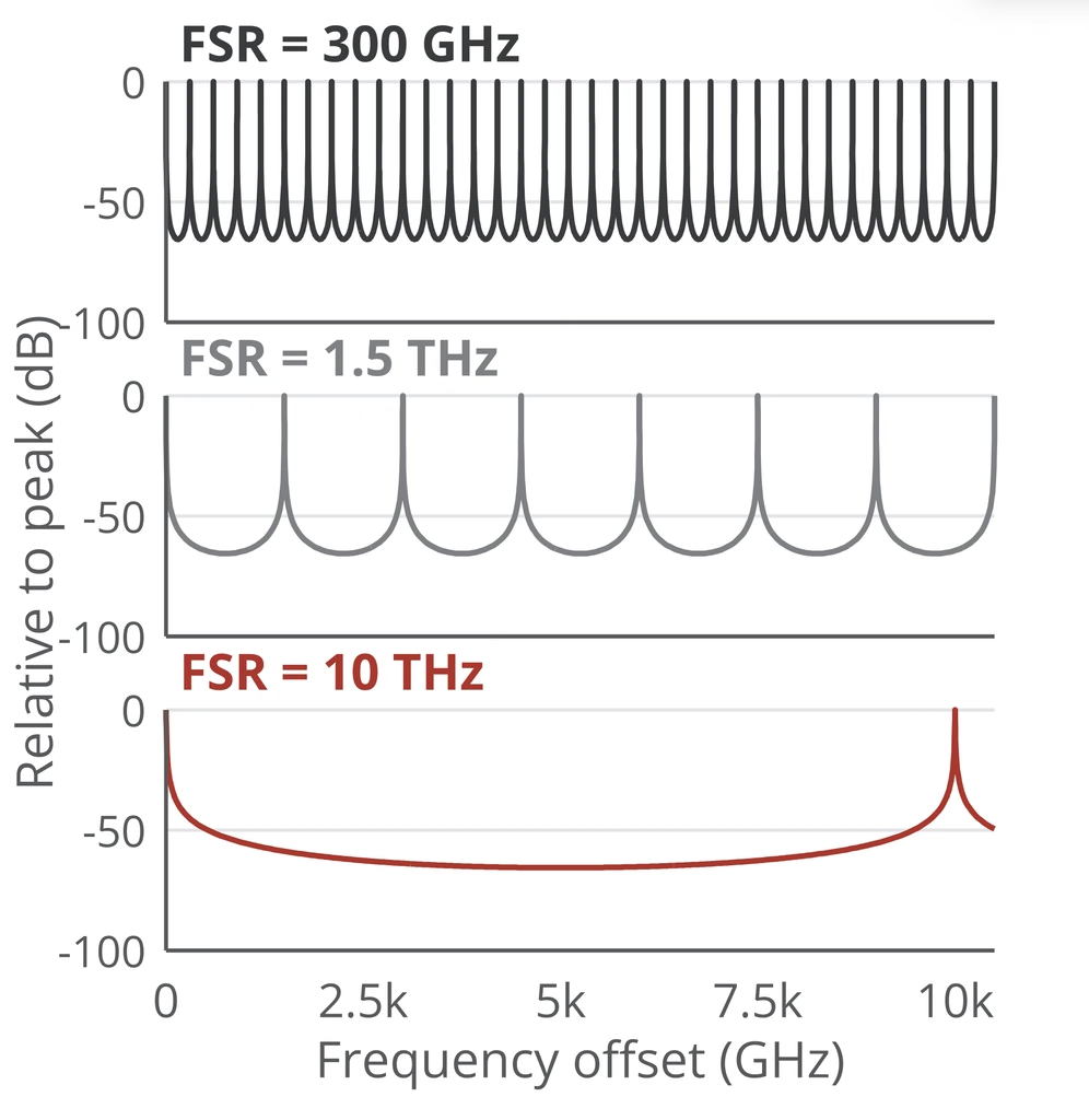
Sidemode rejection
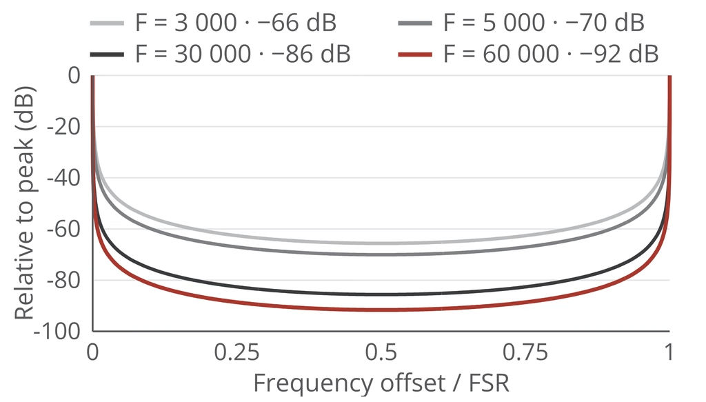
The transmission peaks of a real cavity are not perfectly clean. Residual structure between the main peaks sets the floor of what the filter can reject, and it is the figure that matters when the signal of interest sits next to something much stronger — a weak sideband beside a carrier, a Raman line beside a pump.
Typical sidemode rejection — value and measurement method: to be published.
Voltage tuning
The passband is moved by driving the piezoelectric actuator. Three properties matter in practice, and they are the ones that come up on the second call rather than the first:
Tuning range — how much of the free spectral range is reachable over the full drive voltage.
Hysteresis — the difference between the wavelength reached going up in voltage and coming back down. It matters for any open-loop scan.
Repeatability — whether the same drive voltage returns to the same wavelength after a thermal cycle or a week of operation.
Typical tuning range, hysteresis and repeatability — figures: to be published.
Choosing a configuration
There are two ways in, depending on which end of the problem you start from.
If you start from the linewidth you need to resolve. Your target bandwidth sets the ratio FSR / finesse. Pick the finesse you can support in your mechanical and thermal environment — not the highest available — and the free spectral range follows. A 5 MHz passband can be reached at 0.3 THz with finesse 60 000; the same 5 MHz is out of reach at 10 THz whatever the finesse in the catalogue.
If you start from the span you need to scan. Your scanning window sets the free spectral range, converted to wavelength with the λ² relation above. The finesse then sets the resolution you get inside that window.

In both cases the third number falls out of the first two. That is the whole method.
Catalogue coverage
| Centre wavelengths | 800 nm · 1000 nm · 1560 nm |
| Free spectral range | 0.3 THz · 1.5 THz · 10 THz |
| Finesse | 3 000 · 5 000 · 20 000 · 30 000 · 60 000 |
| Narrowest bandwidth | 5 MHz |
| Catalogue configurations | 45 |
→ The full specification table for all 45 references, with free spectral range and bandwidth given in both frequency and wavelength for every one.
→ Configurations currently in stock
Configurations outside this grid are built to order.
Need help selecting your filter?
Send us your operating wavelength, target bandwidth and spectral span. We can help identify a suitable FSR and finesse combination.